Products
Membranes & processes

Hollow fiber membrane and membrane module
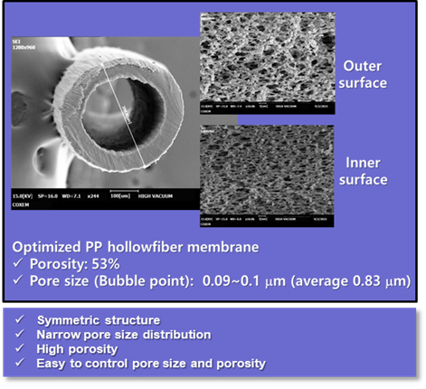
SepraTek has established an innovative thermal induced phase separation (TIPS) process that allows the production of porous polypropylene (PP) hollow fibers with various diameters, pores, and porosities used in membrane contactor and membrane distillation without the need for stretching. SepraTek's TIPS process can produce hollow fiber membranes mechanically strong through braiding. In addition, SepraTek's TIPS process can manufacture porous hollow fiber membrane with chemically stable polymer materials such as PE and PP with which hollow fiber membrane cannot be prepared by the non-solvent induced phase separation (NIPS) process. As shown in the SEM photo below, the PP hollow fiber membrane manufactured by SepraTek's TIPS process is symmetrical in structure, being identical in structure from inner surface through membrane thickness to the outer surface
SepraTek membrane is produced through optimization of pore size, porosity, and mechanical strength for an application, and the production process is also optimized so that all pores in the hollow fiber membrane are interconnected.

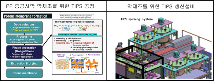
TIPS process and production line for porous PP hollow fiber membrane

Membrane structure design and production process
One of the important factors that determine the membrane separation performance in the membrane contactor process is the membrane module performance. In order to maximize the membrane module performance,
1) the mixing during the liquid flow in the membrane module should be maximized to minimize the concentration polarization, and
2) the liquid flow occurs uniformly to suppress the occurrence of the dead zone.
SepraTek has established a membrane module manufacturing process that is able to maximize its performance by establishing the optimization of the module structure as shown in the flow diagram below.
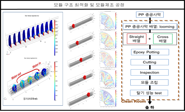
Two types of looming of PP hollow fiber can be used to bundle hollow fibers in module housing: 1) straight looming and 2) cross looming. In the straight looming, PP hollow fibers are arranged in parallel and then are woven with a thread or yarn at a regular interval into PP hollow fiber membrane mat. The woven hollow fiber membrane mat is wound to form a roll of the membrane mat with a certain of diameter. In cross looming, the hollow fibers are crossed each other with a certain angle on a roll of the woven hollow fiber membrane mat as depicted in the picture below.
The purpose to fabricate a bundle of the woven hollow fiber membrane mat is to cause the liquid to flow in transverse mode and to achieve a high degree of mixing of the liquid in flowing in the shell side of membrane module by flowing between hollow fibers in the bundle perpendicularly to the fiber length.
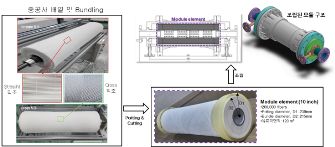
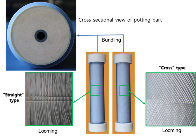
Arrangement and bundling of hollow fiber membrane in module.

Membrane contactor process
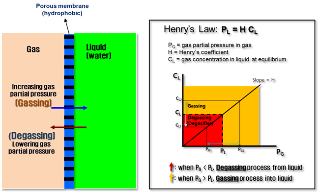
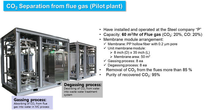
The membrane contactor process is a process in which two streams, i.e., liquid and gas streams, come into contact with each other along the boundary of the porous membrane, and separation occurs when the mass transfer of gas occurs between these two streams. Since water or aqueous solution is used as a liquid flow, if hydrophobic membrane material is used, the liquid cannot pass through the membrane below its breakthrough pressure, but the gaseous components can freely pass through the pores. In the process, if the partial pressure (PG ) of a specific gas component in the gas phase is greater than the equilibrium partial pressure (PL) dissolved in the liquid, the gas component is dissolved from the gas phase into the liquid phase, which is called the Gassing process, and conversely, if the partial pressure of the gas phase is smaller, the component dissolved in the liquid is desorbed into the gas phase, which is called the Degassing process.
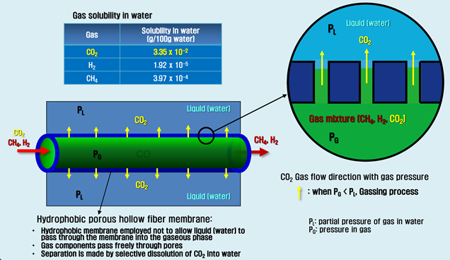
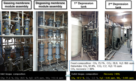
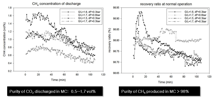
The typical application of the Gassing process is the purification of biogas. The biogas is mainly composed of methane and carbon dioxide, and the solubility of carbon dioxide in water is about 100 times higher than that of methane, so when biogas comes into contact with water in the membrane contactor process, carbon dioxide is selectively dissolved in water through the pores of the membrane, while methane with less solubility is left in the gas stream, harvesting a high purity of methane from the retentate of the gas stream.

SepraTek™ Membrane Contactor Process
SepraTek™ PP hollow fiber membrane is manufactured to SepraTek's module element and placed in a membrane housing with appropriate specifications, such as a pressure vessel, according to the conditions of use. SepraTek™ membrane modules are designed for effective contact between the liquid phase and the gas phase under high pressures (up to 10 atmospheres). SepraTek™ membrane contactor systems are designed and engineered based on systematic simulation and a series of groundworks to maximize membrane performance and the economic value of the membrane process.
 Feature of SepraTek™ Membrane Contactor

No additional chemicals needed to promote the dissolution of gaseous components from the gas mixture to the liquid phase - no contamination
Flexibility in membrane system design through diversification of membrane module arrangement
Effective separation of acidic and basic gases from gas mixtures
Suitable for ultrapure water degassing for use in semiconductor manufacturing or power plants

Application
 Degassing process

Degassing of aqueous solution
Removal of O2 or CO2 dissolved in water
Food & Beverage Industry, Semiconductor Industry, Electricity Power Generation, Chemical Industry, Pharmaceutical Industry
 Gassing process

Dissolving CO2 into water to produce carbonated water.
Dissolving carbon dioxide in water for the production of carbonated water, which is a cleaning solution for the semiconductor cleaning process.
N2 dissolution to reduce the concentration of CO2 in beer in the brewery
Dissolving O2 in water for the production of oxygenated water
 Gassing-Degassing hybrid process

Carbon capture
Removal of CO2, SOx, NOx from flue stream

Removal of VOCs from waste stream discharged from semiconductor manufacturing process
Purification of biogas through separation CO2
Separation of ammoniac N2 from waste water
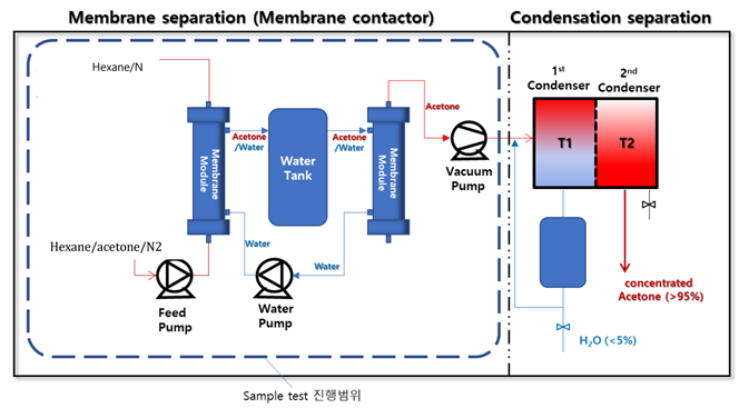
Separation of liquid (hydrophilic/organic) mixture: separation of Hexane/acetone
 Case Studies

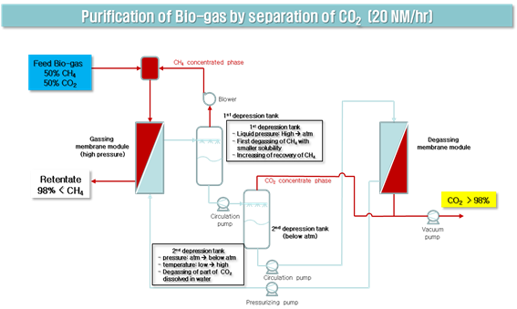
Case I : Purification of biogas
Case III : Separation of CO2 from flue gas
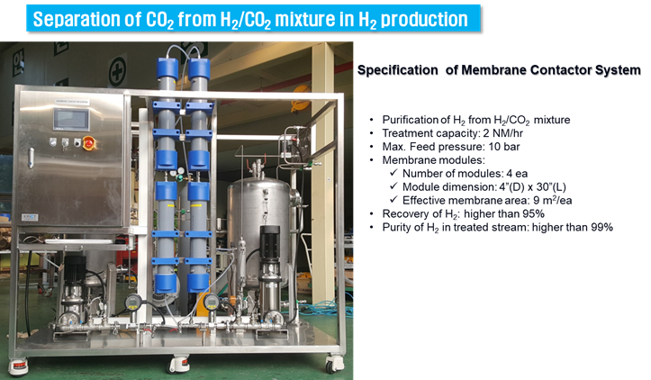
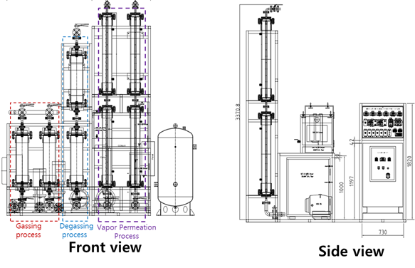
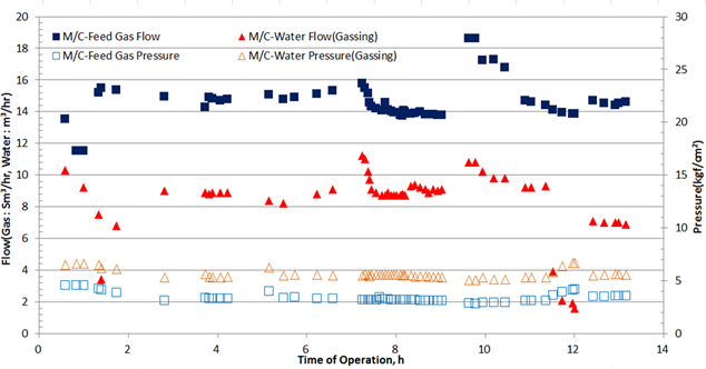
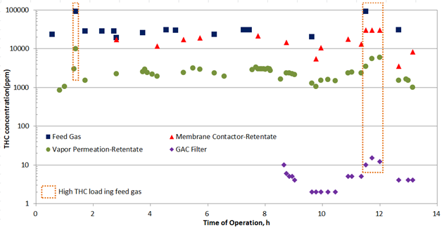
Case IV : Separation of hydrophilic/organic vapor/gas mixture
ADDRESS
TEL
FAX